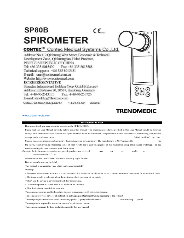
TRENDMEDIC
www.trendmedic.com
Instructions to User
Dear users, thank you very much for purchasing the SPIROMETER.
Please read the User Manual carefully before using this product. The operating procedures specified in this User Manual should be followed
strictly. This manual describes in detail the operation steps which must be noted, the procedures which may result in abnormality, and possible
damage to the product or users.
Failed to follow' the User
Manual may cause measuring abnormality, device damage or personal injury. The manufacturer is NOT responsible
for
the safety, reliability and performance issues of such results due to user’s negligence of this manual for using, maintenance or storage. The free
services and repairs does not cover such faults either.
Owing to the forthcoming renovation, the specific products you received
may
not
be
totally
in
accordance with the
description of this User Manual. We would sincerely regret for that.
Date of manufacture: see the label.
This product is a medical device, which can be used repeatedly.
Warning:
4 To ensure measurement accuracy, it is recommended that the device should not be tested continuously on the same testee for more than 8 times.
4 The testee should breathe out all air during testing, don't exchange air or cough.
4' Don't use the device in environment with low temperature.
4" Automatic power off when there is no operation in 2 minute.
4 This device is not intended for treatment.
The company supplies qualified products to users in accordance with enterprise standard.
The company provides services of installation, debugging and technical training according to the contract.
The company performs device repair in warranty period (a year) and maintenance
The company is responsible to respond to users' requirements in time.
The company reserves the final explanation right to this user manual.
after warranty
period.
Chapter 1 Safety
1.1
Instructions for safe operations
•v* Check the device periodically to make sure that there is no visible damage that may affect its safety or performance. It
is recommended to inspect the device weekly at least. When there is obvious damage, stop using it.
Necessary maintenance must be performed by qualified service engineers ONLY. Users are not permitted to maintain it by themselves. Our
company may, upon request, provide technical support and materials such as components list, legend, calibration details or other materials that
necessary for the maintenance by qualified technical staff.
❖ The device can not be used together with other equipment not specified in User Manual. Only the accessories appointed or recommended by
manufacture can be used.
This device has been calibrated before leaving factory.
1.2
Warning
f
Please don't measure this device with functional tester for the device’s related information.
4
Explosive hazard DO NOT use the device in environment with inflammables such as anesthetic.
4~
Please check the packing before use to make sure the device and accessories are totally in accordance with the
packing list, or else the device may have the possibility of working abnormally.
4" Don't use the device in environment with strong electromagnetic interference, direct breeze source, cold source and hot source.
6
The disposal of scrap device, its accessories and packing (including mouthpiece, plastic bags, foams and paper
boxes, etc.) should follow the local laws and regulations, as improper disposal may pollute the environment.
6
Please choose the accessories appointed or recommended by the manufacturer to avoid damage to the device.
f
Don't use the device with the turbine of other similar products. After replacing the turbine, it is recommended
to
calibrate the turbine before use.
6
When patients use the device,the device is not allowed to be maintained.
4~
Refit of the device is not allowed.
1.3
Caution
A Keep the device away from dust, vibration, corrosive or inflammable substances, high or low temperature and humidity.
A
A
A
A
If the device gets wet or coagulates, please stop operating.
When it is carried from cold environment to warm or humid environment, please do not use it immediately.
DO NOT operate keys on front panel writh sharp things.
High temperature or high pressure steam disinfection to the device is not permitted. Refer to User Manual
inthe
relative chapter (7.1) for cleaning and disinfection.
A Do not have the device immersed into liquid. When wiping the device with medical alcohol, avoid spray any liquid on the device directly.
A
When cleaning the device with water, the temperature should be lower than 60"C.
A
Measured data will be displayed within 5 seconds after finishing the measurement,
the delay timedepends on
the
ending speed.
A
A
A
A
A
If measured data can't be displayed or other abnormal happened during testing, please restart the device.
The device has service life for three years.
The device may suitable for all users, if you can't get good
measurement data, please
stop
using it.
The device needs to be calibrated once per year or less.
The device is intended to test forced vital capacity, use it according
to the User Manual to
A
This user manual contains information about operation instructions and technical specifications.
A
The device can not be operated until half an hour later when it is moved from
getbest results.
the highest or kwest storage
temperature environment to room temperature environment.
A The device needs to be kept out of the reach of children or pets, to prevent animal hair or dirt entering the turbine to affect its use.
A The equipment connected with this device via interfaces should compliance with IEC 60950 or IEC
60601-1.
A Please use medical power adapter when charging the device.
A Applied part: mouthpiece.
A The patient is an intended operator, the patient can measure data and charge battery under normal
circumstances and
maintain the device and its accessories according to the user manual.
A
A
A
A
Mode of operation: continuous operation.
The temperature of cyquipmcnt application part and contactablc part shall not exceed 41 'C.
Non-transit-operable.
The mouthpiece is disposable, do not open its package if not use.
1.4 Contraindication
1.4.1
A
A
A
Absolute contraindication
The
one with MI or shock in recent 3 months;
The
one with serious cardiac function unstable or angina pectoris in recent 4 weeks;
The
one with massive hemoptysis in recent 4 weeks;
A The one who needs medication in epileptic seizure;
A The one with uncontrolled hypertensive disease (SYS>200mmHg, DIA>100mmHg);
A
The
one with aortic aneurysm;
A
The
one with serious hyperthyroidism.
1.4.2
Relative contraindication A
Heart rate >120 bpm;
A The one with pneumothorax or giant pulmonary bulla and not plan for surgical treatment;
A Pregnant woman:
A The one with tympanic membrane perforation (need to block the ear canal of affected side before taking measurement);
A The one w'ith RTI recently (less than 4 weeks);
A The one with hypoimmunity;
A Patients of respiratory communicable disease or infectious disease shall not take lung function examination in the Acute stage. The one
with low immunity is not appropriate to take the examination also. If it is necessary, disease control and protection shall be strictly
followed.
Chapter 2 Overview
forced Vital Capacity is the maximum expiration after taking a full breath, it's an important examination content in chest-lung disease and
respiratory health, and it is an indispensable testing project in modem Pulmonary inspection. At the same time, it has great significance in respiratory
diseases diagnosis, dilTcrential diagnosis, treatment evaluation and selection of surgical indications. Thus, w'ith the rapid development of clinical
respiratory physiology, clinical applications of lung capacity inspection arc also gaining popularity.
The device is small in volume, low in power consumption, convenient in operation and portable. With high-definition display screen, the device
is concise and fashion. To take a measurement, it is required to breathe in fully, and seal the lips around the mouthpiece and then breathe out all air as
fast as possible, the screen will directly display the measured parameters, such as Forced Vital Capacity(FVC), Forced Expired Volume in one
second(FEVl), Peak Expiratory Flow(PEF). This device has a high accuracy and repeatability.
2.1
Features
1)
2.8" screen, clear in displaying, low in power consumption.
2)
Simple to operate, easy to understand.
3)
Small in volume, convenient in carrying and testing at anytime.
4)
Large capacity rechargeable lithium battery, environmental protection.
5)
Specific test for FVC, orientation analysis.
2.2
Application scope
The SPIROMETER is a hand-held equipment for examining lung function. The device is fit for hospital, clinic, family for ordinary test(FVC, FEV1,
FEV1/FVC, PEF, etc.). It's only required that the user operates it according to user manual, no need for specialized training, so the operation of the
device would be as simple and easy as possible.
2.3
Environment requirements Transport
and storage environment:
Temperature: -30 'C~+55 'C Relative humidity: <95
%
Atmospheric pressure: 500 hPa-1060 hPa Operating
Environment:
Temperature: +10 'C--+40 "C Relative Humidity: <80
%
Atmospheric pressure: 700 hPa-1060 hPa
Take a deep inspiration, seal the lips around the mouthpiece and blast all air out as forcefully as possible, the exhalant gas transforms to rotary airflow
by turbine, then makes the blade rotate. The infrared emission tube and reception tube inside the device aim at the blade, when the blade rotates, the
reception tube judges and transforms the light signal received, form the various signal related to blade rotation, via processing by amplification circuit,
form the recognizable signal by SCM, via SCM processing, it will transform to each measurement parameter which will be displayed by the screen.
Chapter 4 Technical Specifications
4.1
Main functions
♦ Forced Vital Capacity (FVC), Forced Expired Volume in one second (FEV1), the ratio of FEV1 and FVC (FEV1%), Peak expiratory flow (PEF),
25% flow of the FVC (FEF25), 50% flow of the FVC (FEF50), 75% flow of the FVC (FEF75) and average flow between 25% and 75% of the
FVC (FEF2575) can be measured. Besides, the testee condition can be showu by the ratio of the measured value and the predicted value.
Flow rate-volume chart, volume-time chart display.
Data memory, delete, upload and review'.
Trend chart display.
Indicating exhalation duration in real-time Personal information(height. age, gender, etc.)
can be set.
Chapter 3 Principle
Health status indication.
Data transmission by Bluetooth and USB.
Low voltage indication.
Rechargeable lithium battery for power supply, with charging indication.
Calibration function.
Real-time clock can be set and displayed.
Automatic power off function.
4.2
Main Parameters Volume
Range: 0-10 L Flow' rate range: 0
L/s~ 16 L/s
Volume accuracy: ±3 % or 0.05 Lfw'hichever is greater)
Flow rate accuracy: ±5 % or 0.2 L/s(whichever is greater)
EMr Group I I'j Wcrking mode'
continuous working
According to the MDD K/42, the dan;Miration ai'lilts medical device: -] J Type of
protection against electric shook: internally powered equipment
Degrc-i i if prutcdiun against dor Irie shock: type L5J-' -17-pli-.nl pan III
Degree of protection provided by enclosure: W22
Battery: 3.7V, 220OmAh. rechargeable lithium battery,discharge cycle not Less than 300 times.
n.1 View i,:' [In fi ant panel
Exhale duration ULdLcator light (fi)
Tutbuie
States iurl ii,-:irkn liglu J ■ ■)—i!f—-—HMWN
. J *RtTL’RN
t ON'OFF-d----------------------------------------------------------------I ----------------------------------------------------------------------------►
HEASURE/CONFIHM
Figeio l-l Frent panel view
S.IAsthnhly mill iliaiLlHiillhLi
l)Turbiiic assembly: align the the turbine to the lufhine hole on the shell, gently insert it Lithe bottom, cloclcwioc rotate to lock h.
2;Qijrt'Lur disassembly: tourUcrcJockivisc rotate the vjjbine. yently pull :L out.
3)btoullipiiK;e assembly: inserl une er.d of the mouthpiece into the turbine purl directly.
Note: The tutbine should be installed into (he correct position from (be front side of the device, see the mark; on the device.
?.3 Accessaries
1)
A User Manml
2)
A t SH cable
3)
A mouthpiece I disposable)
■1)A power adaptef (optitmal)
5)PC software
b)A note clip loplitmul)
Male: If other pawcr adapters arc used, the foHrming requirements should he met: output voltage is DC e V, current is n a less than I A. and the power
adapter should comply with IFT fiOSSl) ar l Ft LttfeOl-l.
ClujKer t Operating Guide
ft.I OprrjJin^ 111l-I In ill 6.1.1
Power MIL'vff
(I) Aflcr ii^sonr.hly. LDII^T press ON/OFF key to turn on th^ dcvjcc.
(?.■ Under "ON" ilste, kinsP™* ON.OFF key ta turn il off, ft. 1.1
Mi'jMirniiL'nl
CO After IUJTUEIJ; on due device, it will Locate in Selective interface shown js 1'igjne 2. press UP or DOWN key lo select’No", press
CONFIRM key to enter Testing interface, shown as Figure 3 {Note: if select ''Yes", it will cuter Parson*! information intstfaea k> edit
information, after exiting, it will return to Testing interface-),
(?) Jn I esting inter kite, breath hr fully, seal the lips around the mo'.nlipiece end bias: all air out as forcefully as possible :n Llic ahortcst time,
the orar^c indicator on (op r.cht comer ivill (licltcr at a certain li&iucr.cy. Then wait lor a fow seconds, the device will cntei Man paiajisctei
W)¥
53:111C
W-J3
li& you rant La cilii.3013-
I5:| I
11
[tip
'MJ-IH-.
!■ ii -: .
■■■
interface as shown ill Figured.
I igurc 2 Selective interface
I i^ure 3 Testing
interface
6.13 hi
aim
interface
IJdLIJ
' ;:'V? NO. IJ
ct rracra .
0-11.
.&SL /am \
j_r ww '
aig jgjj
Rutiu of IIWII^IKJ i :IIILL |L>
PLIf
L. rSL/v1
lift
predicted Vlhe
FCT1/FVC 7(j. 0t HUT
FEFlE
I. STUt
PEF50
I, LI L/s\ Hlft
l-l>7»
Jift
:■
L. L LI.
FEF2675 I. 191. As TW'
1
Thu |)fuilri;Lutl 1 aiue is EI
iu [u] lii l Lk Tulud
(.Mniisjsondin^ Ion defined
cmditiflB (jcjider, cue. liL‘ialn.L'(L.
tine assured). ll ns u guiluinl value
figured IWaln piLT^mrtur interface a. >1ain parameter interface: display S p-DTELn.ictiM values
and the tafia of cadi parameter to i:s oomespoajdmf pretliilad value. The ratio reflects health status, carntt settings of persona] Information is the Lev
to ulnaln accurate ratio. Resides, ibis interface also displays piywet icon., twreiit time, ease number and lioalili slatos indicator, as shown m Figure 4.
h. Health status indicator: indicates the measured state, displays the icstec health condition by the ratio of measured value to the predicted
value vividly, i c. The HBnparwjn of measures: value with MIL reference value n same situation, il it. rvd when the vulue is lower Lhan hO"':. which
means that the tesiee should druw attention and go Lo hospital .r. lime: yellow m range of il)yV-!H)yi, it means 1lta: the testee should draw attention:,
it is green when the value is higher than e'T'hj, which is normal. The determinate item of health stilus indicator is optional, it can be set m '‘Denote
value" under LlT>ai* mtmagarriLitit”.
e. "I low rate-vol r.me chart" irnd "Vclume-time chart" shewn as J'hguM 5 will appear after pjcssuig Ui1 or DOWN key
6.13;i,hiPersonal information
aim l.riKln Mc:|U inteffllCe, Select Pt fd infwnisiisn" lo tnw its -;i)h-menU *S shown in Figure'. in ■.'■lii-. li NSerCmi
interface
edt patient inkniralian (Note; Under iekctive interline as shown in Figure 2. selecting "Yes" will enter Persor-iil iril'nrjnatiMi irilerfaci: ton I
,L
(1)
(Jim1 number
"NijtntrtK" is the currant ease number. For aximpl;, if you are the 215|L testee, the '‘Number" will he 2,1. Case number tan uvtriase UKHUllcalJy. no
need tu set munuulLy,
(2)
Gender setting
Use IN' or DOWN key lo select "Genderpress CON I IRM Ley and III’ or DOWN key to select 'MALE" or "FEMALE", then press CONFIRM key Ln
ictum to Lhc Personal information interfaco,
(3)
Sid tings n1 jigu, bright. weight
Select "Age" to adjust the age as shown in Figure H Press UP or DOWN key la charge the value, die value will i-icrciise decrease i after pttssinillP nr
DOWN key cnee, (ben pres* CONFIRM key b> reftim to Personal information interface.
Thu modification of "hMjbt’1 and’Weighr is similar m the “Age", Adjustable i.inga:
"Age": 6-100
"Height*: S0-240 cm
"Weight": L 5-250 Jig
POT son il 1 rLl'ciruil ion
Hunter
ItCtwhfT
It
MALE
llcijjht '!an>
ICLBIH (kg)
ftyurt 1 on
Saaker
BOT
Exit
LSI
.50
Era:
NO
m
Figure S Are udiuslmen: interface
(4) Kuo* [ion sc-rling
The ir.oiiiiliatL-Dn step of “Lepual ion" is llte same Iu the "Gender’. The
equation of
predicted
vulue ear. to
set La
"Fquiitiar." item. including "HCSC". " K N Dili SON " and ’USA".
In) Sri Ling nf ter and hi til
The modification steps a-J “Smoker" anil "RDT" arc ihe
siune lu
ihe
"Gender",
in v/Jiich smoker
and UJJ1
LnFormatK-n can he edited.
I Ah Exit
In Persona] information interface, Selecl "Exit" or press KO'URN lo remm to Menu interface. b.LFlitu
111:1:1 an i'me ill
Select "]>s1u management - i:i Menu interlace ta er.Lcr its pib-mcnu sbosvn as Figure 9, Llie.a "Review Function", ' Trend CtUVB", Dull#* Ua-Ji" a:itl "Denote
VIIIIIL" can Ire selected.
1111:
Li ■
,
1
,
1 ii ms
Jll.K-llV.J.l
D:il a HtiiiaiptfiPii L
*■ '
Trflcd
riiTifl
T* re 11 ft
illiijr-o
liiir.T
Deiiotfc
Value Ex i. [
frfyrim klelte
foar.fi OHMIC
[fclLa
ililllilRI'IH'lll
Value Exit
Rnfim Pnncsinr
Figure 9 Data tnanugemetd iiderfaoe
figure 1 h Case selection interface
11 > Hex jew function
Select "Review Function" in Data Management interface Lo select Ihe case number as shown in Figure 10, press UP 111 DOWN key to change
the value. press COM FIRM k:y to enter Main interface lo display ihe hitloricbl dala, tinitiiuiowiy iMejs up or now\ key in Main interlace to review
the data in adjacent case nwufbei. prise Confirm key Do rcfirni m Menu interlace.
[2 | Trend curve
Select “I'rend Curve" Q to enter LTcnd curve selection interface, as shown in JTcure It. after selecting Ihe (UtlOKler, p_ess CONFIRM key to enter
Trend Cur*# display interface, as shown Lr. J lgtire 12, the figure is a summary of all stored date mining at the selected perimeter, n displays the irend charge
vividly, whu h is convenient for tester to compare. If there are loo much dm a, press DP or DOWN kei in ihr curve n browse all dala trend in him, press
Figure 15 Sellings interface
(5)Exh
Jn Data Management interface, select "Hxir" or press RK'I URNf to return to Menu interface,
c.
Settings
Select "Settings'1 in Menu interface to enter the setting interlace as shown in Figure 15. Under this interface, settings uf language, HLuetouth
on/off, time and calibration, and view device information can be reahreJ.
(1) Language
Select "Language" in Settings interface, then press UP or DOWN key to select "English" or "41 £" (if the device docs not have built-in
language selection function, the operation is invalid)
(2) Bluetooth
After moving to "Bluetooth", press CONFIRM key to select "0N7"0FF" to turn on/off the Bluetooth module (optional function, if there is
no Bluetooth module in the device, the operation is invalid).
[}) lime setting
Select "Time" to enter its setting interface, select "Year" to display current year as shown in Figure 16, press UP or DOWN key to change
the value, after selecting, press CONFIRM key to save.
The operation steps of "Month", "Day", "Hour", "Minute" and "Second" are the same to the "Year".
Under Calibration interface, push the syringe once, the device will display "Please repeat", then push the syringe once again. After continuous
three correct operations, the calibration is succeed, and the device will display "OK!". Finally the interface will jump to the former interface before
calibration (The former interface: if calibrating after measuring, it will return to Settings interface; if calibrating before measuring, it will return to
Testing uiterfjce.j.
If the device displays "Error!", it indicates something wrong with the operation or the syringe selects improper volume, please confirm that
the calibration volume is correct, then repeat calibrating until succeeding. If you need to stop calibrating, just press the CONFIRM key to exit to the
interface before calibrating.
Select "Adjust" in Calibration interface to display the current calibration value as shown in Figure 19. Press UP or DOWN key to change the
value, press CONFIRM key to save.
Mote:
4? The value determines the accuracy of measurement, please do NOT change it randomly.
After replacing the turbine, calibration shall be applied Tor inputting parameters of new turbine, which guarantees the
accuracy of measurement after replacing.
Q> When replacing the turbine, please use tile one recommended by our company.
£y Improper calibration may affect the measurement accuracy, please be careful.
Figure 15 Sellings interface
FL^iirc 15 Calibration adjustment interface In Calibration selection interface,
select "Exit” or press RETURN to return to Settings interface.
(5)
About
Select "About" in Settings interface to enter its sub-menu to check the device name and software version, then press CONFIRM or
RETURN key to return to Settings interface.
(6) Exit
In Settings interface, select "Exit” or press RETURN to return to Menu interface.
d.
I’imer off
Select "Power Off in Menu interface to turn off the device.
Note: If there is no operation within 2 minutes, the device will power olT automatically.
i.F.iit
In Menu interface, select "Exit" or press RETURN to return to Mam interface, if the measurement is not completed before entering Main
interface, it will return to Testing interface.
6.1.6
Charging
The device will automatically enter the charging interface when it is charging. Under this interface, all keys arc unfimctiomal, and the device can’t be
used.
Two method'. Ihr charging:
1
Charge the device by tenner ting to a computer via USB cable.
2
Charge the device by connecting to the power adapter.
A Do .NOT use the device when charging.
A The indicator light on the top left of the device is displayed in orange when the device is charging, and it turns to green alter the device is fully
charged.
A When the device is charging, please place the device where easy to cut n(T from the mains supply. After the device is fully charged, unplug the
power adapter to disconnect the device from mains supply.
6.1.7
Data transmission
1)
Install PC software into a computer, after that, connect the device with the computer by the equipped USB cable, open the software and turn
on the device, then data transmission is available.
2)
The device has Bluetooth transmission (unction. After powering on the device, the Bluetooth is in ON state, the Bluetooth icon is displayed
on screen. At this time, the device can be searched and connected with other devices. When the connection is built successfully, the device displays data
transmission icon, and this icon flickers during data transmitting.
6.2
Attention
APlcasc check the device before using to confirm that it can work normally.
AAutomatic power off when there is no operation in two minutes.
Alt is power supplied by rechargeable lithium hatteiy.
Alt is recommended that the device should be measured in room.
AExccssivc ambient light may aficct measurement accuracy. It includes fluorescent lamp, dual ruby light, infrared heater, direvt sunlight, etc.
A Intense activity of the subject or clcctrosurgical interference may also affect the accuracy.
APleasc clean and disinfect the device aflcr using according to the User Manual (7.1).
APIease use the USB cable recommended by our company if it is necessary to replace the USB cable.
Chapter 7 Maintenance, Transportation and Storage
7.1
Cleaning and disinfection
Use medical alcohol to wipe the device enclosure, nature dry or clean it w'ith a clean and soft cloth. It's necessary to clean the turbine periodically
for accuracy, keep the diaphaneity of the luccncy part, and keep it away from sundrics(such as hair or lesser sediment). Immerse the turbine in
disinfectant after use, after a few minutes, clean it with clean water and air dry (but don't make the turbine rinsed with water directly), this disinfection
method will not bring pollution to
environment. (Note: The disinfectant is 75% alcohol).
7.2
Maintenance
1)
Please clean and disinfect the device before using according to the User Manual(7.1).
2)
Please charge the device when the screen displays low voltage(the battery' power is
3)
Charge the battery in time after it is fully discharged. If the device is not used for a long time, it should be charged every 6 months, which
CD).
could greatly extend the battery service life. Users arc forbidden to replace the battery by themselves, if necessary, place contact the local service center
or our company.
4)
The device needs to be calibrated once a year(or according to the calibrating program of hospital). It can be performed at the state appointed
agent or just contact us for calibration.
7.3
Transportation and storage
1)
The packed device can be transported by ordinary conveyance or according to transport contract. The device can not be transported mixed
with toxic, harmful, corrosive materials.
2)
<95%.
The packed device should be stored in room with no corrosive gas and good ventilation. Temperature: -30",C~t-55°C; Relative Humidity:
ipter 10 Farnmelers
Trouble
Possible Reason
for a long time, and the dm a can'i be
The Start Speed is too Low, the device
does not measure.
Device malfunction.
displayed.
Liata enor
Operate the device falsely.
The device can’t finish measurement
Solution
Remeasure according to the L.'ser Manual,
Remeasure or restart the device.
Operate ths device according to the User Manual.
'['lie device can not be powered on.
Device malfunction
Please contact ihe local service center.
Low voltage or no voltage.
Please charge the device.
Device damaged.
Please contact the local service center,
Normal
The display disappears suddenly.
The device is se1 to automatic power off when
there is no operation in 2 minutes.
Low voltage
Please charge [lie device.
The use time is too short after
The device is not fully charged.
Please charge the device.
charging.
Device batleiy damaged.
Device battery damaged.
Please contact the local service cenler.
Please contact the local service Center.
The device Cun not be lUlly charged a
Her charging more than 10 hours.
chapter 9 Symbols
Symbol
■
■
IB
CD
a
a
Moaning
Full battery
Low battery
Health status indicate! bar
Anticlockwise rotate to unlock the turbine
Clockwise rotate 1o lock the turbine
Do nol rc-use
jf
T
X
f
11
Do nol insert
Atmospheric pressure limitation
Temperature limitation
Humidity limitation
f
$1$
53
Meaning
Keep diy
Nnn-innij'.mg radiation
Serial nnmbei
^■wj |
Date of manufacture.
«J
Manufacturer
IS
Li
0
X
o
Type EF applied part
For indoor use only
Class ]1 equipment
WEEE (2002/96/EC)
F ragile, handle with Care
(!)
Refer to instruction manual/booklet
This way up
iBCbterl
European Representative
The first number.2; Protected against solid foreign
\P22
Symbol
objects of Id.5 mm <1* and greater The second
number 2: Protection against vertically railing
water drops when LNCT.OSL 'ItE
C
^
mo
Standby
This item is compliant with Medical Device
Directive 93/42/EEC of June 14. l'J^3, a directive
of the European Economic Cnmmun ity.
52
pter S Troableshootidfi
\TL-JHumL parameters:
Parameter
Description
Unit
FVC
Forced vital capacity (total expiratory volume)
1
FEVl
Forced Expiratory Volume in one second
L
PFF
Peak expiratory flow
1 j's
FEV1/FVC
Forced cxpiratoiy rate in one second. FEV1/FVC -100
%
FEF25
Forced expired flow at 2.5% oil'W
iVi
FEF50
Forced expired flow at 50% of FVC
L.s
KEK157S
11
L/s
FEF7?
Forced expired flow at 75% of FVC
orced expiratory How between 25% and 7 5 % of FVC
L/s
G uid u n ce and manufacturer’s declaration electromagnetic emissions - for all EQUIPMENT and SYSTEMS
Guidance and manufacturer’s declaration - electromagnetic i niiiuiin
Tlic SPHOFs is intended lor use in Ihe electromagTieUc cnviroruficnl specified below. Tin: customer of 1hc user of the SPfiOB sliould assure
that it is used in such and environment.
Fmission test
Compliance
RF emissions CISPR 11
Croup l
Fleet ro mag nr tic er vi run mi: nt — guidance
The tiPfciJE! uses RF energy only for its internal function, therefore its Kh emissiotis are very
low and arc not likely to cause any interference in nearby electronic equipment.
I'bc SP8UI3 is suitable for use in all establish merits, including domestic and those directly
RF emission C1SPR 11
Class R
connected to a low voltage power supply nelwork which supplies buildings used for do me stir
purposes.
Guidance and manufacturer’s declaration - electromagnelie immunity for ail EQUIPMENT and SYSTEMS
Guidance and manufacturer's declaration-electromagnetic immunity
The SPSOB is intended for use in the electromagnetic environment specified below. The customer or the user of S PS OR should assure that d
i.s used in such an etivirnnmetd.
Immunity test
Compliance level
Elect re magnetic environment - guidance
IEC 60601 test level
P.leetnrsluiic discharge (F5D) I EC
±<5 kV contact +15
±k kV ixHitact = 15 kV
610<MM-2
kV air
air
Floors should be wood, concrete or ceramic tile. If
floor are covered with Synthetic muleiial, 1he
relative humidity should be at least 50%.
30/Virj
30A/m
Power frequency (50/60 FI/) magnetic
Mains power quality should be that of a typical
fie hi IEC 61000-4-S
commercial or hospital environment.
NOTE
TRENDMEDIC
Guidance and manufacturer's declaration - declrtimaguctic immunity for EQUIPMENT and SYSTEMS
Guidance and manufacturer's declaration - electromagnetic immunity
1 lie SP80IJ is intended for use irr the electromagnetic environment specified below. 1 lie customer 01 tlie usei of Spy OB should assure that it is
used in such an environment
Immunity test
IEC 6U6U1 Test level
Compliance
Electromagnetic environment - guidance
level
Portable and mobile Rf comm uni cations equipment should Lie used no
closer to any pair of the SI1 MOB. including cables, Ihijn lhe
recommended separation distance calculated from the equation applicable
to the frequency of the transmitter.
Recommended separation distance
d
=\¥V*
L£'- 80 Mil/to 800 MHz
d= 4r 800 MHz to 2.5 GHz
Radiated RF ItiC
61000-4-3
lOV/m
SO Milz to 2.5 Gliz
10 V/m
LiJ
Where P is the mas im um eutpnr power rating of the transmitter in watts
(W) according to tbe tr arm mi iter lnarrrrfacbirer and ;l is the roCr i rrn i
re tided separation distance in metres tin).
Field strength* from rlsed RF transmitters, as determined by an
electromagnetic site survey," should he less than the compliance level in
each frequency range.n Interference may occur in the vicinity of
equipment marked with the following: symbol:
NOTE 1 A( SCI Mil/ and SftO Mil/. Ibc higher frequency range applies
NOTE 2 J'hcse guidelines may not apply in all situations. Electromagnetic propagation is alfecled by absorption and reflection from structures,
objects and people.
f ield strengths from fixed transmitters, sneli as base stations for [ailio (cellular/cordless) telephones and land mobile radios, amateur
radio, AM and FM radio broadcast and TV broadcast cannot be predicted theoretically with accuracy. To assess the electromagnetic
environment due to lined RF transmitters, an electromagnetic site survey should be considered. If the measured field strength in the location
in which the SP80B is used exceeds the applicable RT compliance level above, ibe SP80R should be observed to verily normal opera lion. If
abnormal performance is observed, additional measures may be necessary, such as reorienting or rcloealing the SPSOB.
KtconniKaded separation distintn bemetsn poll able and mobile RF communications equipment mu) tin- KQIJIPMICNT dr SYSTEM
for
EQUIPMENT or SYSTEM ________________________________________________________________
Recommended separation distances between portable unci mobile HFcommunications equipment anil llu: SPKOH
The STfcdB is intended for use in an electromagnetic environment in which radiated lilr' disturbances are Controlled Tht customer Or the user o
IT he SPHOH tun help prevent eke-tri.imugnctie interference by maintaining u mini mum dislanee between portable unit mobile RF
vormnunieatkuu; equipment (transmitters) and dm SPhdR as recommended below, according to the maximum output power oJ'the
communications equipment.
Rated niuyirunm output
Separation distance according In frequency uftransmitter fra)
power of transmitter
(W)
811 M i l / to 81111 M i l /
SUOMELzto 2 . 5 (ill/
J= —#
L£iJ
A.
a
.01
0.036
0.069
0.1
0,111
0.222
i
0.351
(1.(199
10
L. 107
2.214
100
3.501
6.999
For transmitters rated at a maximum output power not listed above, the recommended separation distance d in metres (m) ear he estimated using
the equation applicable to Ihe Irvqueney of the transmitter. when1 P is the maximum output power rating of the transmitter in watts (W) according
to the transmitter manufacture1.
KOTF. 1 A1 SO Ml and 80b Mil/, I lie sepaMlion distance for I be higher frequency range applies.
NOTtdThesc guidelines may Jiot apply in all situations. Llcctiomaguctie propagation is affected by absorption and reflection from structures,
objects and people.


