Ltspice Analysis of Double- Inductor Quadratic Boost Converter in Comparison with Quadratic Boost and Double Cascaded Boost Converter
advertisement
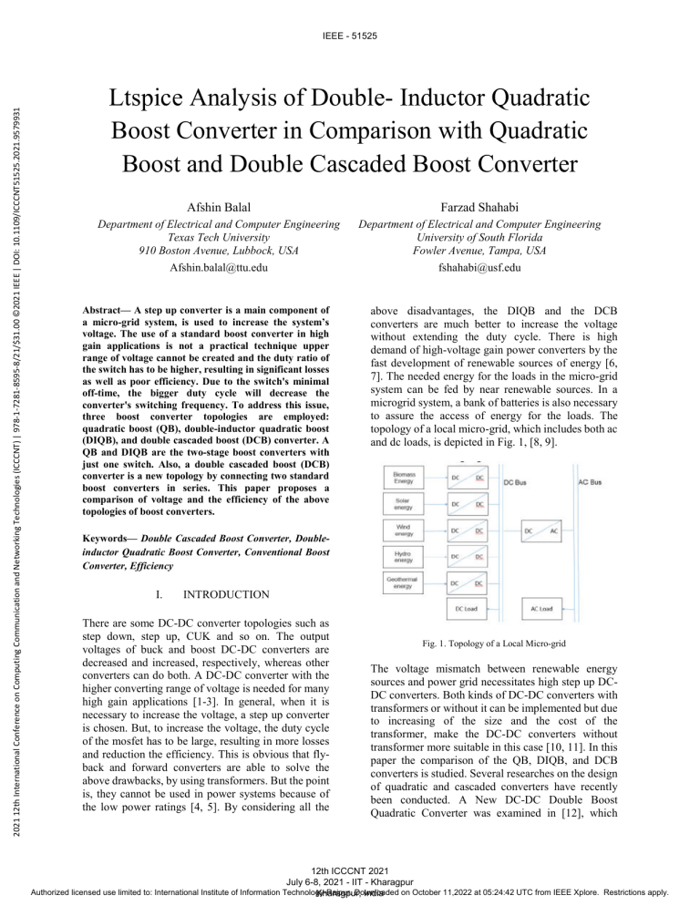
2021 12th International Conference on Computing Communication and Networking Technologies (ICCCNT) | 978-1-7281-8595-8/21/$31.00 ©2021 IEEE | DOI: 10.1109/ICCCNT51525.2021.9579931 IEEE - 51525 Ltspice Analysis of Double- Inductor Quadratic Boost Converter in Comparison with Quadratic Boost and Double Cascaded Boost Converter Afshin Balal Farzad Shahabi Department of Electrical and Computer Engineering Texas Tech University 910 Boston Avenue, Lubbock, USA Afshin.balal@ttu.edu Department of Electrical and Computer Engineering University of South Florida Fowler Avenue, Tampa, USA fshahabi@usf.edu Abstract— A step up converter is a main component of a micro-grid system, is used to increase the system’s voltage. The use of a standard boost converter in high gain applications is not a practical technique upper range of voltage cannot be created and the duty ratio of the switch has to be higher, resulting in significant losses as well as poor efficiency. Due to the switch's minimal off-time, the bigger duty cycle will decrease the converter's switching frequency. To address this issue, three boost converter topologies are employed: quadratic boost (QB), double-inductor quadratic boost (DIQB), and double cascaded boost (DCB) converter. A QB and DIQB are the two-stage boost converters with just one switch. Also, a double cascaded boost (DCB) converter is a new topology by connecting two standard boost converters in series. This paper proposes a comparison of voltage and the efficiency of the above topologies of boost converters. above disadvantages, the DIQB and the DCB converters are much better to increase the voltage without extending the duty cycle. There is high demand of high-voltage gain power converters by the fast development of renewable sources of energy [6, 7]. The needed energy for the loads in the micro-grid system can be fed by near renewable sources. In a microgrid system, a bank of batteries is also necessary to assure the access of energy for the loads. The topology of a local micro-grid, which includes both ac and dc loads, is depicted in Fig. 1, [8, 9]. Keywords— Double Cascaded Boost Converter, Doubleinductor Quadratic Boost Converter, Conventional Boost Converter, Efficiency I. INTRODUCTION There are some DC-DC converter topologies such as step down, step up, CUK and so on. The output voltages of buck and boost DC-DC converters are decreased and increased, respectively, whereas other converters can do both. A DC-DC converter with the higher converting range of voltage is needed for many high gain applications [1-3]. In general, when it is necessary to increase the voltage, a step up converter is chosen. But, to increase the voltage, the duty cycle of the mosfet has to be large, resulting in more losses and reduction the efficiency. This is obvious that flyback and forward converters are able to solve the above drawbacks, by using transformers. But the point is, they cannot be used in power systems because of the low power ratings [4, 5]. By considering all the Fig. 1. Topology of a Local Micro-grid The voltage mismatch between renewable energy sources and power grid necessitates high step up DCDC converters. Both kinds of DC-DC converters with transformers or without it can be implemented but due to increasing of the size and the cost of the transformer, make the DC-DC converters without transformer more suitable in this case [10, 11]. In this paper the comparison of the QB, DIQB, and DCB converters is studied. Several researches on the design of quadratic and cascaded converters have recently been conducted. A New DC-DC Double Boost Quadratic Converter was examined in [12], which 12th ICCCNT 2021 July 6-8, 2021 - IIT - Kharagpur Authorized licensed use limited to: International Institute of Information Technology-Raipur. Downloaded on October 11,2022 at 05:24:42 UTC from IEEE Xplore. Restrictions apply. Kharagpur, India IEEE - 51525 demonstrates the suggested converter's high static gain and low voltage switching. Also, [13] looked at a transformer-less Double Quadratic Boost that can be used as a high step-up converter in numerous industries. The recommended converter in [14] looked at a high-gain Cascade Boost Converter by uses a softswitching strategy to improve efficiency. For nonisolated Interleaved Double Dual Boost Converters, the paper [15] proposes a robust LQR control approach based on LMIs. As a result, the suggested controller has a more predictable dynamic behavior. The study [16] Analysis and Design of Quadratic Boost, which can provide substantial gains at low duty ratios, was used. II. BOOST CONVERTERS IN HIGH GAIN APPLICATIONS To increase the voltage of the renewable sources of energy to higher needed voltage, a step-up converter is used to enhance the voltage to the suitable voltage [1719]. A. Conventional boost converters In Fig. 1, the circuit of conventional topology for the boost converter is shown. Fig. 3. Two modes of the Boost Converter In the on-state mode, when switch is on, the inductor is charged by the DC input voltage, which lead to the increase of the inductor current. On the other hand, in the off-state mode of operation, switch off, the stored energy in inductor will go through the capacitor through the diode. The relationship between the duty cycle, inductor value, and the capacitor value are as follows: 𝑉𝑜𝑢𝑡 1 = (1) 𝑉𝑖𝑛 1−𝐷 𝐷𝑉𝑖𝑛 𝑇𝑆 𝐿= (2) ∆𝐼𝐿 𝐷𝑉𝑜𝑢𝑡 𝑇𝑠 𝐶= (3) ∆𝑉𝑐 𝑅 1 𝑓𝑠 = (4) 𝑇𝑠 Where Vin is the input voltage, 𝑉𝑜𝑢𝑡 is the output 𝑓𝑠 is the switching frequency, ∆𝐼𝐿 is the output ripple current, and ∆𝑉𝑐 is the output ripple voltage. B. Double cascaded boost (DCB) converters Implementing two conventional boost converters in series leads to new topology known as double cascaded boost converter which is shown in Fig. 4. DCB has an input voltage source, two independent mosfets, diodes, capacitors, and two inductors L1 and L2 [20]- [21]. Fig. 2. The topology of the Boost Converter As it is shown in Fig. 2, the boost converter has two structure modes of operation. Fig. 4. The Topology for the Double Cascade Boost Converter As it is shown in Fig. 4, Double Cascade Boost Converter has two structure modes of operation. 12th ICCCNT 2021 July 6-8, 2021 - IIT - Kharagpur Authorized licensed use limited to: International Institute of Information Technology-Raipur. Downloaded on October 11,2022 at 05:24:42 UTC from IEEE Xplore. Restrictions apply. Kharagpur, India IEEE - 51525 this problem can be solved by utilizing DIQB converter which it will be designed and illustrated in the next section. III. Fig. 5. Two modes of the Double Cascade Boost Converter In the mode 1, when the first switch is on, second switch remains off, the current through inductor L1 is increasing by the input voltage source and stores the energy. In the mode 2, when the second switch is on, S1 is off, the output of the first part is now the input of the second part, the inductor L2 will be charged through the DC voltage from the first part, and stores the energy [22]. The equations can be seen below: 1 1 𝑉𝑜𝑢𝑡 = (1 − 𝐷1 ) (1 − 𝐷2 ) 𝑉𝑖𝑛 𝑇𝑠 = 𝐿1 = 𝐿2 = 𝐶1 = 𝐶2 = 1 𝑓𝑠 (6) (7) 𝐷1 𝑉𝑎 𝑇𝑆 ∆𝑉𝑐1 𝑅 (9) 𝐷2 𝑉𝑜𝑢𝑡 𝑇𝑆 ∆𝑉𝑐2 𝑅 The QB and DIQB converters shown in Fig. 6 and 7, are the two stage boost converters with just one switch. This topology has two inductors and two capacitors. The input voltage of the QB converter is the same with DIQB [23, 24]. By implementing double inductor quadratic, the voltage will be increased about 30% more. (5) 𝐷1 𝑉𝑖𝑛 𝑇𝑆 ∆𝐼𝐿1 𝐷2 𝑉𝑖𝑛 𝑇𝑆 ∆𝐼𝐿2 DOUBLE INDUCTOR QUARATIC BOOST (DIQB) CONVERTER Fig. 6. The topology of Quadratic Boost Converter (8) (10) Where D1 is the duty cycle for the first boost, D2 is the duty cycle for the second boost, L1 is the inductor value of the first inductor, L2 is the inductor value of the second inductor, C1 is the capacitor value of the first capacitor, C2 is the capacitor value of the second capacitor, and 𝑉𝑎 is the output voltage for the first boost converter. However, the problem with the above topologies is that they cannot produce a suitable higher voltage, which is needed for high gain application. So, Fig. 7. The topology of Double Inductor Quadratic Boost Converter As it is shown in Fig. 8, Quadratic Boost Converter has two structure modes of operation. 12th ICCCNT 2021 July 6-8, 2021 - IIT - Kharagpur Authorized licensed use limited to: International Institute of Information Technology-Raipur. Downloaded on October 11,2022 at 05:24:42 UTC from IEEE Xplore. Restrictions apply. Kharagpur, India IEEE - 51525 (a) Fig. 8. Two modes of the QB In the mode 1, the current of inductor L3 and L4 are increasing by DC voltage source and store the energy. In the mode 2, the energy of inductors L3 and L4, feeds the capacitor. The relationship between the duty cycle, inductors value, and the capacitors value are as follows [25]: 1 𝑉𝑜𝑢𝑡 = (1 − 𝐷)2 𝑉𝑖𝑛 𝐿1 = 𝐿2 = 𝐷𝑉𝑖𝑛 𝑇𝑆 ∆𝐼𝐿1 𝐷𝑉𝑖𝑛 𝑇𝑆 ∆𝐼𝐿2 𝐶1,2 = IV. 𝐷𝑉𝑖𝑛 𝑇𝑆 (1 − 𝐷)∆𝑉𝑐 𝑅 (11) (b) (12) (13) (14) SIMULATION AND RESULTS The DCB, QB, and DIQB converters are analyzed by Ltspice. The circuit parameters for all the topologies are the same. Fig. 9, indicates the output current and voltages of the three topologies. (c) Fig. 9. Output currents and voltages of three topologies; (a) double cascaded boost converter, (b) quadratic boost converter, (c) double inductor quadratic boost converter As it shown in Fig. 9, the voltage of the DIQB converter is 114 volts which is 30% higher than the output voltage of both cascaded and quadratic converters. 12th ICCCNT 2021 July 6-8, 2021 - IIT - Kharagpur Authorized licensed use limited to: International Institute of Information Technology-Raipur. Downloaded on October 11,2022 at 05:24:42 UTC from IEEE Xplore. Restrictions apply. Kharagpur, India IEEE - 51525 Fig. 10. Inductor currents of the QB topology Fig. 10, indicates the current of L1 and L2 of the QB, in which IL1 is 3.35 A and IL2 is 1.67 A. conversion range. Moreover, a coupled inductor was adopted to quadratic boost for further increase in the double inductor quadratic boost converter. The steady state analysis by Ltspice indicated that the double inductor quadratic boost topology, voltage gain is higher than the quadratic and cascaded boost converter and this increased gain was achieved without increasing the switch stress. As a result, we can claim that all the three proposed converters can be a suitable choice for the high voltage gain ratio application. In addition, the efficiency analysis shows that the best topology is the double cascaded boost converter. A double inductor quadratic boost converter with a higher efficiency can be the future research. However, the operation with a single switch such as the double inductor quadratic boost converter is very attractive because of the high gain voltage even though its efficiency can be a little less. REFERENCES [1] Fig. 11. Switch voltage stress of the DIQB topology In Fig. 11, the stress on the switch of DIQB has been shown. The stress on switch in DIQB converter is almost the same with both DCB and QB. The performance of each converter has been studied. Table 1 shows the efficiency of each converter which is calculated with the below equation. [2] [3] [4] 𝑃𝑜𝑢𝑡 𝐸𝑓𝑓𝑖𝑐𝑖𝑒𝑛𝑐𝑦 = 𝑃𝑖𝑛 (15) [5] Where Pout is the output power and Pin is the input power. Table 1 Efficiency of different converters with the same circuit parameters Type of converter Efficiency Double Cascaded boost 94.65 Quadratic boost converter 89.12 Double inductor quadratic boost converter [6] [7] 87.27 [8] V. CONCLUSION In this paper, a comparison of three topologies of DC/DC converter is presented. Compared to conventional boost topology, double cascaded and quadratic boost converter offer significantly wider [9] Alassi, A. and A. Massoud. High-gain DC-DC converters for high-power PV applications: Performance assessment. in 2018 IEEE 12th International Conference on Compatibility, Power Electronics and Power Engineering (CPE-POWERENG 2018). 2018. IEEE. Salvador, M.A., et al., Methodology for synthesis of high‐gain step‐up DC–DC converters based on differential connections. International Journal of Circuit Theory and Applications, 2021. 49(2): p. 306-326. Balal, A. and M. Murshed, Implementation and comparison of Perturb and Observe, and Fuzzy Logic Control on Maximum Power Point Tracking (MPPT) for a Small Satellite. Journal of Soft Computing and Decision Support Systems, 2021. 8(2): p. 14-18. Mohseni, P., et al., An Optimal Structure for High StepUp Non-Isolated DC-DC Converters with Soft-Switching Capability and Zero Input Current Ripple. IEEE Transactions on Industrial Electronics, 2021. Rezaie, M. and V. Abbasi, Ultrahigh Step-Up DC-DC Converter Composed of Two Stages Boost Converter, Coupled Inductor and Multiplier Cell. IEEE Transactions on Industrial Electronics, 2021. Talebitooti, R. and M. Morovati, Study on TVD parameters sensitivity of a crankshaft using multiple scale and state space method considering quadratic and cubic non-linearities. Latin American Journal of Solids and Structures, 2014. 11(14): p. 2672-2695. Adami, A., M. Morovati, and H. Ahani, DESIGN A GAIN SCHEDULED FUZZY CONTROLLER FOR DISTRIBUTED PARABOLIC SOLAR COLLECTORS. Annals of the Faculty of Engineering HunedoaraInternational Journal of Engineering, 2021(1). Tamalouzt, S., et al., Performance analysis of a microgrid system composed of renewable energy sources with hybrid energy storage system, in ELECTRIMACS 2019. 2020, Springer. p. 257-266. Moaveni, B., F.R. Fathabadi, and A. Molavi, Supervisory predictive control for wheel slip prevention and tracking of desired speed profile in electric trains. ISA transactions, 2020. 101: p. 102-115. 12th ICCCNT 2021 July 6-8, 2021 - IIT - Kharagpur Authorized licensed use limited to: International Institute of Information Technology-Raipur. Downloaded on October 11,2022 at 05:24:42 UTC from IEEE Xplore. Restrictions apply. Kharagpur, India IEEE - 51525 [10] [11] [12] [13] [14] [15] [16] [17] [18] [19] [20] [21] [22] [23] [24] [25] Lopez-Santos, O., et al., Quadratic boost converter with low-output-voltage ripple. IET Power Electronics, 2020. 13(8): p. 1605-1612. Gholizadeh, H., et al., Design and Implementation a Single-Switch Step-Up DC-DC Converter Based on Cascaded Boost and Luo Converters. Energies, 2021. 14(12): p. 3584. De Sá, F.L., D. Ruiz-Caballero, and S.A. Mussa. A new DC-DC double Boost Quadratic converter. in 2013 15th European Conference on Power Electronics and Applications (EPE). 2013. IEEE. Totonchi, N., H. Gholizadeh, and E. Afjei. A Transformer-less Double Quadratic Boost Converter with Positive Output Polarity and Non Zero Input Current. in 2020 28th Iranian Conference on Electrical Engineering (ICEE). 2020. IEEE. Lee, Y.-S., W.-C. Lin, and L.-C. Yu. Design of a cascade high gain soft-switching boost converter. in 2015 IEEE 11th International Conference on Power Electronics and Drive Systems. 2015. IEEE. Amritha, A. and A.D. Pai. A comparative study of controllers used for Interleaved Double Dual Boost Converter. in 2015 International Conference on Control Communication & Computing India (ICCC). 2015. IEEE. Veerachary, M. and N. Kumar, Analysis and design of quadratic following boost converter. IEEE Transactions on Industry Applications, 2020. 56(6): p. 6657-6673. Dehnavi, S.D., et al., Employing interface compensators to enhance the power quality in hybrid AC/DC microgrids. Ciência e Natura, 2015. 37(6-2): p. 357-363. Dehnavi, S.D. and E. Shayani, Compensation of Voltage disturbances in hybrid AC/DC Microgrids using series converter. Ciência e Natura, 2015. 37(6-2): p. 349-356. Mumtaz, F., et al., Review on non-isolated DC-DC converters and their control techniques for renewable energy applications. Ain Shams Engineering Journal, 2021. Hu, X., et al., A hybrid cascaded DC–DC boost converter with ripple reduction and large conversion ratio. IEEE Journal of Emerging and Selected Topics in Power Electronics, 2019. 8(1): p. 761-770. Balal, A., S. Rukh, and S. Balali, Designing a Dual Active Transformer DC-DC Forward Converter for DC Micro-Grid Applications Using LTSPICE. International Journal of Applied Engineering Research, 2021. 16(4): p. 327-331. Choi, J., G. Lee, and F.-s. Kang. Cascaded dc-to-dc converter employing a tapped-inductor for high voltage boosting ratio. in IECON 2015-41st Annual Conference of the IEEE Industrial Electronics Society. 2015. IEEE. Choudhury, T.R. and B. Nayak. Comparison and analysis of cascaded and quadratic boost converter. in 2015 IEEE Power, Communication and Information Technology Conference (PCITC). 2015. IEEE. Mortazavi, S.M.B., et al., Optimal planning and management of hybrid vehicles in smart grid. Ciência e Natura, 2015. 37: p. 253-263. Maheshwari, M. and M. Arounassalame. Control of integrated quadratic boost sepic converter for high gain applications. in 2019 Fifth International Conference on Science Technology Engineering and Mathematics (ICONSTEM). 2019. IEEE. 12th ICCCNT 2021 July 6-8, 2021 - IIT - Kharagpur Authorized licensed use limited to: International Institute of Information Technology-Raipur. Downloaded on October 11,2022 at 05:24:42 UTC from IEEE Xplore. Restrictions apply. Kharagpur, India

